


Categorization:Harness Component
In notebook computers, industrial cameras, high-speed display devices, AI vision equipment, and other high-density electronic products, the internal space of the devices is becoming increasingly compact, while the signal transmission rate continues to rise. Traditional ribbon cables and ordinary multi-core cables are facing more limitations in high-speed signal transmission, electromagnetic interference resistance, and space wiring, so ultra-fine coaxial cable harnesses (Micro-Coaxial Harness) have become an important solution for internal signal connections in high-speed and miniaturized electronic devices. The I-PEX 82862-100B-02-D introduced in this article belongs to the I-PEX CABLINE®-CA series evaluation ultra-fine coaxial cable harness, with the corresponding application features of 20Pin, Micro-Coaxial ultra-fine coaxial cable, AWG40, length 300mm, and 1-N wire position definition. The wire end is equipped with a connector model of 20634-120T-02. For engineers, the value of this kind of cable harness is not just "connecting multiple signals together," but to achieve signal integrity, impedance control, EMI suppression, mechanical reliability, and assembly consistency simultaneously within a limited space; for purchasers, it is necessary to further pay attention to whether the product can be compatible and replaced according to the original design of the connector interface, Pin number, wire position definition, length, and electrical requirements, thereby reducing supply risk and comprehensive procurement cost.
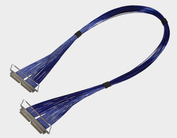
Understanding the ultra-fine coaxial cable bundle starts with the structure of a single ultra-fine coaxial wire. A typical Micro-Coaxial ultra-fine coaxial cable usually consists of a central conductor, an insulating layer, a shielding layer, and an outer sheath. The central conductor is responsible for high-speed electrical signal transmission, the insulating layer is responsible for isolating the conductor and affecting the overall dielectric characteristics, the external shielding layer is responsible for the important electromagnetic shielding function, and the outermost protective structure is used to ensure the mechanical stability of the cable during processing, bending, assembly, and use. Compared with ordinary wires, the important advantage of the coaxial structure lies in the relatively complete shielding system around the signal conductor, which allows the signal transmission path to have better electromagnetic environment control capability. For high-speed differential signals, conductor size, insulating material, shielding structure, cable outer diameter, and manufacturing consistency will all affect characteristic impedance, insertion loss, return loss, and crosstalk performance. Therefore, engineers should not only look at the single parameter such as "AWG40" when choosing an ultra-fine coaxial cable bundle, but should comprehensively consider high-speed interfaces, transmission rates, cable length, impedance requirements, wiring space, and connector matching relationships. The I-PEX 82862-100B-02-D uses a 20Pin, AWG40, 300mm, 1-N cable bundle configuration, and uses the 20634-120T-02 as the cable end connector model, which means that when carrying out domestic substitution or secondary design, it is necessary to ensure the consistency of cable specifications, terminal structure, and Pin position correspondence.
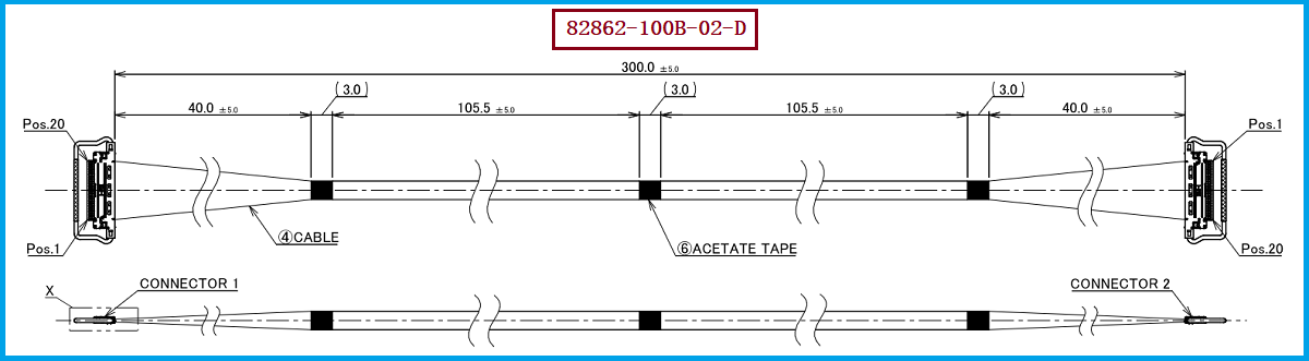
For extremely fine coaxial cable assemblies, the wire itself is only a part of the entire component. What truly determines its direct application to equipment includes connectors, termination processes, and wire position definition. I-PEX 20634-120T-02 belongs to the CABLINE®-CA series 20Pin Plug Housing, corresponding to a high-density connection scheme with 0.4mm spacing; CABLINE®-CA is designed for miniaturization and features mechanical lock, shielding, and multi-point grounding, suitable for high-speed signal connection scenarios. Therefore, when replacing I-PEX 82862-100B-02-D, engineers should focus on verifying the connector model and matching structure, the number of 20Pin, AWG40 wire specification, 300mm wire length, 1-N wire position definition, and both ends termination methods. At the same time, according to the actual equipment, confirm the wire bending direction, exit direction, shielding continuity, and assembly space. It is particularly important to note that 1-N is not a simple "wire sequence" concept but represents the wire position connection relationship at both ends of the cable assembly. During the replacement and development process, it is necessary to confirm each pin based on the original product drawings, samples, or equipment interface definitions. For purchasers, it is recommended to confirm "model+Pin number+wire diameter+length+connector+wire position definition" as a complete cable assembly specification during the quotation stage, rather than relying solely on connector models or cable material numbers for procurement. Our company can provide: I-PEX 82862-100B-02-D compatible replacement cable assembly solutions. We can match and develop ultra-fine coaxial cables, connectors, and termination processes according to the actual equipment interface and technical requirements of customers, providing domestic substitution support for engineering verification, sample trial production, and mass supply.
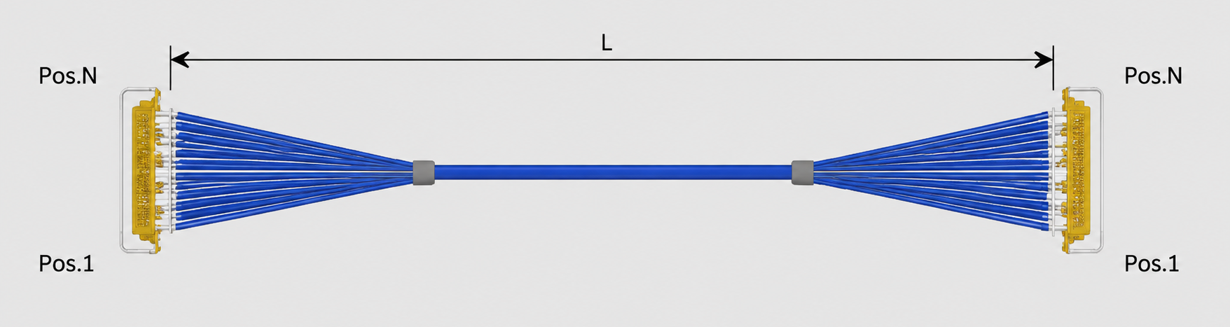
In the selection process of extremely thin coaxial cable assemblies, engineers are recommended to prioritize confirming the actual signal type and transmission requirements before determining the cable structure and connector scheme. For high-speed display, high-speed camera, or other high-speed digital signal applications, it is also necessary to pay close attention to characteristic impedance, signal attenuation, crosstalk, shielding continuity, and termination quality. For coaxial cable assemblies like the I-PEX 82862-100B-02-D with 20 pins, AWG40, 300mm, and 1-N, alternative solutions cannot simply achieve "the connector can be inserted," but should also ensure that mechanical dimensions, electrical performance, wire position, and actual assembly methods are as matched as possible to the original scheme. For purchasers, it is recommended to divide the alternative project into three stages: "sample verification," "small batch verification," and "mass production introduction." First, confirm the mechanical compatibility between the connector and the equipment, then verify the high-speed signal performance and reliability, and finally assess the consistency, delivery time, and cost of mass production. Especially in domestic substitution projects, it is necessary to clearly distinguish between "connector compatibility" and "entire cable assembly compatibility": the former addresses interface issues, while the latter must also resolve issues related to cable material, termination, shielding, wire position, length, and manufacturing consistency. For customers with needs for domestic substitution, second supplier development, or cost optimization, they can directly use I-PEX 82862-100B-02-D + 20634-120T-02 + 1-N as the technical communication benchmark. Our company will match it according to the original equipment samples, drawings, or equipment interface requirements provided by the customer, reducing the development cycle and verification cost of redesigning the cable assembly.
“Without the consent or authorization of this site, no one shall reproduce, reprint, distribute, cite, change, broadcast or publish the content in whole or in part in any form, nor shall there be any other violation of the copyright of this site.