


Categorization:Harness Component
Inside high-speed electronic devices, extremely thin coaxial cables not only handle signal transmission tasks but also need to face the complex electromagnetic environment within the device. Thin coaxial cables are usually composed of a central conductor, insulating medium, shielding layer, and an external protective structure, with the shielding layer located around the signal conductor. Its main function is to provide a relatively stable electromagnetic transmission environment for high-speed signals, while reducing the impact of external electromagnetic interference on the signal and minimizing the radiation interference generated by the signal on surrounding lines. For engineers, the shielding layer is not simply adding a layer of metal material but, together with the central conductor, insulating material, and impedance design, it constitutes a complete high-speed transmission structure. Therefore, as the internal lines of laptops, display modules, cameras, and other high-density electronic devices become increasingly dense and the high-speed signal rates become higher, the importance of the shielding structure for signal integrity becomes more prominent. I-PEX CABLINE®-SS is positioned for high-speed data transmission applications, and the official product information shows that its product details and testing use Micro-Coaxial Cable AWG#40, 45Ω, 100mm, and provide a test result of 16Gbps/Lane.
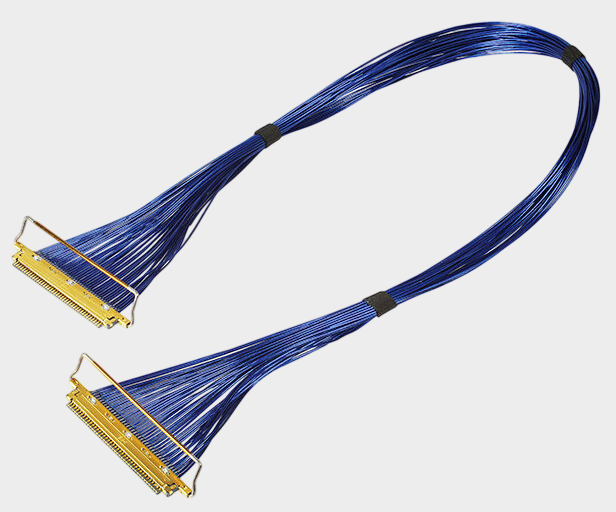
From the perspective of engineering design, the shielding layer can be understood as an electromagnetic isolation structure that surrounds the signal conductor. When multiple sets of high-speed signal lines are arranged simultaneously in a narrow space, interference between adjacent lines may occur; at the same time, the power module, processor, display circuit, and wireless communication module in the device may also form a complex electromagnetic environment. The ultra-fine coaxial structure, through the collaborative design of the center conductor, medium, and peripheral shielding structure, makes the signal transmission path more explicit and helps control the transmission characteristics. It should be noted that the shielding layer cannot solve all EMI or signal integrity problems alone; the actual effect also depends on the shielding continuity, termination method, connector structure, impedance control, wiring length, and grounding design. Therefore, when engineers are selecting or developing alternative harnesses, they cannot only confirm whether there is a shielding layer but also pay attention to whether the entire harness structure from the ultra-fine coaxial cable to the connector end remains consistent. CABLINE®-SS uses a 0.4mm contact spacing, vertical right-angle structure, and horizontal outlet design, and provides a W-Point double-point structure; the official documentation also clearly states that the Full EMI Shielding (ZenShield®) of this series is “No”, therefore CABLINE®-SS itself cannot be described as having a full shielding structure, and the shielding performance should be evaluated mainly from the specific Micro-Coaxial Cable and harness termination structure.
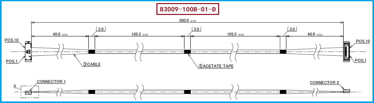
The corresponding product model is I-PEX 83009-100B-01-D, which belongs to CABLINE®-SS 10P HARNESS. The official I-PEX product page specifies this model as 10Pin, Micro-Coaxial 40AWG, 300mm, and 1-1 wire position definition; the corresponding wire end uses the connector model 20373-R10T-06. The specific engineering drawings you provided further indicate that this harness uses Micro-Coaxial Cable AWG#40, 50Ω, BLUE, with a total of 10 wires, a total length of 300.0±5.0mm, and 1-1 straight-through wire position definition. This means for engineers, when carrying out compatibility development, it is not enough to simply copy "10PIN, 300MM"; attention must also be paid to the specific wire material, shielding structure, wire sequence, and assembly structure at the connector end; for purchasers, it should be considered as important identification information when inquiring suppliers and confirming samples, including 83009-100B-01-D, 20373-R10T-06, 300MM, AWG#40, 50Ω, and 1-1.
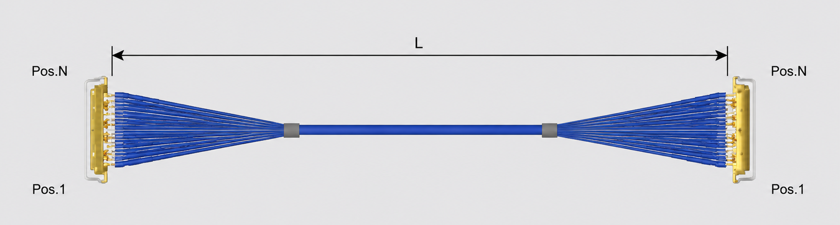
For the compatible alternative of I-PEX 83009-100B-01-D, the engineering side recommends first confirming the 10PIN interface quantity, 300MM length, 1-1 line position definition, and 20373-R10T-06 connector matching relationship, and then further confirming the AWG specification, impedance, outer diameter, shielding structure, and termination process of the ultra-fine coaxial cable. If the application belongs to high-speed signal transmission, impedance and signal integrity verification should be combined with the actual system speed, and cannot directly equate the 45Ω high-speed test conditions on the CABLINE®-SS page to the 50Ω specification of the actual 83009 cable material. I-PEX official data shows that CABLINE®-SS covers 10, 14, 20, 30, 32, 35, 40, and 50 Pins, and provides different length and 1-1, 1-N cable assembly models, so the alternative development can be customized to match the specific equipment structure. Our company can provide: I-PEX 83009-100B-01-D compatible alternative cable assembly solution, which can be developed around 10PIN, 300MM, 1-1, AWG#40, and corresponding connector structure for ultra-fine coaxial cable assembly, and samples are verified for the shielding of the wire material, termination structure, dimensions, and electrical performance, providing corresponding cable assembly solutions for engineering introduction and procurement substitution.
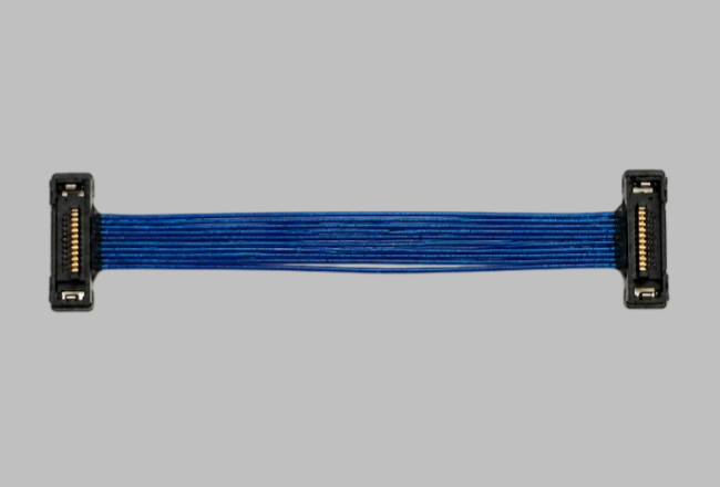
“Without the consent or authorization of this site, no one shall reproduce, reprint, distribute, cite, change, broadcast or publish the content in whole or in part in any form, nor shall there be any other violation of the copyright of this site.