


Categorization:Harness Component
In high-speed signal transmission systems, extremely thin coaxial cables not only bear the signal connection function but also directly affect signal integrity, transmission loss, and the system's EMI/EMC performance. For engineers, when selecting extremely thin coaxial cables, in addition to focusing on wire diameter, length, temperature resistance, and connector matching, it is essential to pay special attention to the characteristic impedance (Characteristic Impedance). Impedance is not simply understood as the DC resistance of the wire but rather the high-frequency transmission characteristic formed by the conductor, insulating layer, shielding structure, and geometric dimensions when high-speed signals propagate through the cable. The common characteristic impedances of extremely thin coaxial cables include 45Ω, 50Ω, 85Ω, 90Ω, and 100Ω, among others. The specific values need to be matched according to the high-speed interface standards, signal architecture, connectors, and terminal equipment, and cannot be determined solely by the AWG wire diameter. Taking the I-PEX 82997-100B-01-D extremely thin coaxial cable assembly solution introduced in this article as an example, the cable specification used with it is AWG#40. The high-speed transmission reference test in the product information of the I-PEX CABLINE®-CA II PLUS uses AWG40 Micro-Coaxial Cable, 45Ω impedance, and 100mm cable length for testing, and verifies the high-speed transmission capability of 32Gbps/lane PAM4. Therefore, for engineers who need to design high-speed signal systems, it is not only the "AWG40" parameter that should be considered, but also the comprehensive confirmation of the matching relationship between impedance, cable length, connector, Pin definition, and high-speed signal protocols.
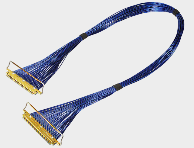
I-PEX 82997-100B-01-D belongs to the CABLINE®-CA II PLUS 60Pin ultra-thin coaxial cable assembly product line, with the cable end equipped with a connector model of 20680-060T-01, using AWG#40 ultra-thin coaxial wire. From the perspective of structure and application, the core value of this type of cable assembly lies in completing multi-channel high-speed signal transmission within limited internal device space through the smallest possible wire diameter and high-density connection structure. The accompanying CABLINE®-CA II PLUS connector features a 0.4mm Pitch design, and has ZenShield® full shielding structure and mechanical locking design, which is conducive to controlling electromagnetic interference during high-speed transmission and reducing the risk of connector loosening due to improper assembly or equipment vibration. For space-saving products such as laptops, tablets, high-speed display modules, industrial vision equipment, VR/AR devices, and high-speed camera equipment, using AWG#40 ultra-thin coaxial wire can help achieve a more thin and flexible internal connection scheme while meeting high-density wiring requirements. For engineers, it is particularly important to pay attention to the impedance matching between the wire material, PCB, connector, and terminal chip; for purchasing personnel, it is necessary to further confirm the Pin count, wire length, termination connector, wire sequence, shielding method, and batch consistency of the cable assembly to avoid replacement solely based on "same appearance".
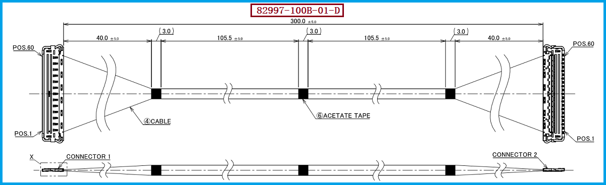
In actual projects, there is no unified answer to "What is the common impedance of ultra-fine coaxial cables?" Different applications have different requirements for impedance, for example, 50Ω schemes are often seen in radio frequency and some communication applications, while high-speed differential signals, display signals, and other high-speed digital interfaces may adopt different differential impedance systems. At the same time, the single-ended characteristic impedance of ultra-fine coaxial cables themselves is also affected by factors such as the size of the center conductor, the dielectric constant of the insulating material, the thickness of the insulating layer, the structure of the shielding layer, and manufacturing tolerances. Therefore, engineers cannot simply think that "AWG#40 is a fixed impedance" when replacing harnesses. Especially for high-speed ultra-fine coaxial cable harnesses like I-PEX 82997-100B-01-D, it is recommended to use the original design's high-speed signal requirements as a basis, and to match and verify the characteristic impedance of the wire material, connector interfaces, and the overall signal chain. In other words, a truly reliable alternative solution is not simply "finding a wire of the same thickness," but to try to maintain the original product's wire material structure, impedance characteristics, connector interfaces, Pin Assignment, wire length, and electrical performance, thereby reducing the risk of high-speed signal integrity.
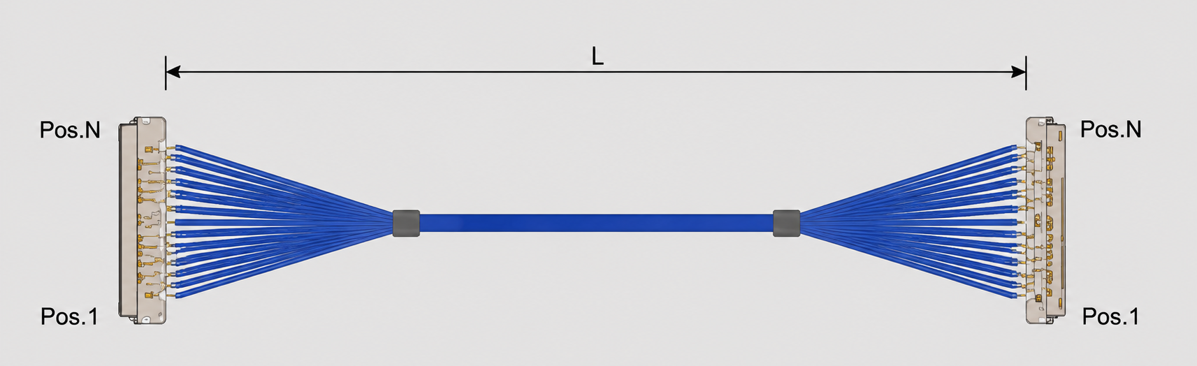
For engineers and procurement personnel involved in the domestication of connector, supply chain optimization, cost control, or the introduction of a second supplier, if the existing scheme uses I-PEX 82997-100B-01-D, it is recommended to first confirm the original cable's 60Pin connection method, AWG#40 wire specification, actual cable length, pin definition, and high-speed signal requirements. At the same time, pay close attention to the structural dimensions, terminal arrangement, locking form, and assembly method of the wire end connector 20680-060T-01. On this basis, carry out impedance and electrical performance verification of the ultra-thin coaxial cable rather than just replacing it according to the model or appearance. For bulk purchasing, attention should also be paid to conductor material, insulating material, shielding layer structure, outer diameter tolerance, terminal crimp/welding process, wire sequence consistency, and finished product testing capability. Our company can provide I-PEX 82997-100B-01-D compatible cable replacement solutions. We can develop compatible cable replacement solutions that use AWG#40 ultra-thin coaxial wire and 20680-060T-01 wire end connectors according to the customer's equipment structure and electrical requirements. We can also match and develop cable length, pin definition, output direction, termination method, and overall cable structure according to the actual project requirements. For high-speed application projects, it is recommended to focus on impedance, continuity, voltage resistance, insulation, signal integrity, and high-speed transmission performance verification at the sample stage to improve the reliability of the replacement solution introduction.
“Without the consent or authorization of this site, no one shall reproduce, reprint, distribute, cite, change, broadcast or publish the content in whole or in part in any form, nor shall there be any other violation of the copyright of this site.