


Categorization:Harness Component
The core value of extremely fine coaxial cable束 lies in "miniaturization, high-density, high-speed signal transmission, and good shielding capability," and it is not used for carrying high-power electrical power transmission. Taking I-PEX 82878-100B-02-D as an example, this product belongs to the CABLINE®-CX II With Cover 40Pin extremely fine coaxial cable束, using 46AWG Micro-Coaxial Cable, with a length of 200mm, and it is a 1-N wire sequence structure; its matching cable end connector is 20974-040T-01, with a connector of 40PIN and 0.25MM spacing. According to I-PEX official data, the contact spacing of this connector is only 0.25mm, the signal Pin count is 40, and the reference transmission speed can reach 5 Gbps/lane NRZ, and it supports high-speed signal applications such as USB 3.1 Gen 1, V-by-One HS 1.4, HDMI 1.3, eDP, and MIPI. From the working principle, the internal structure of the extremely fine coaxial cable束 consists of a central conductor, an insulating layer, and a shielding layer, where the central conductor is responsible for signal transmission, and the outer shielding layer is mainly used to suppress external electromagnetic interference and reduce cross-talk between signals. When high-speed differential signals pass through the cable束, a reasonable impedance structure and shielding structure can help maintain signal integrity. Therefore, when engineers design high-speed cameras, display modules, internal high-speed connections in notebooks, or other space-limited electronic devices, they are more concerned about insertion loss, impedance, cross-talk, EMI, bending performance, and connection reliability, rather than simply pursuing how much power the cable束 can carry.
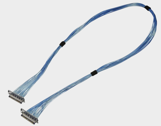
For engineers, the biggest contradiction between "ultra-fine coaxial" and "high power" comes from the conductor cross-sectional area. The finer the wire diameter, the smaller the effective cross-sectional area of the central conductor usually is, and its ability to carry current continuously is also limited. If the cable bundle is made to carry a current beyond its rated range for a long time, it may produce more obvious Joule heating, i.e., P=I²R, and the heat generated will increase rapidly as the current increases. At the same time, the internal space of the ultra-fine cable bundle is very limited, and the heat dissipation conditions cannot be simply understood as those of ordinary thick cables. Therefore, when selecting, one cannot simply consider "40Pin number is large" and believe that it can carry a large total power. The rated current data provided by I-PEX for CABLINE-CX II With Cover also illustrates this point: AWG46 is 0.1 A/contact, AWG44 is 0.15 A/contact, and AWG39 is 0.3 A/contact, and all are noted as data under the condition of up to 40 contacts. Therefore, for engineers, ultra-fine coaxial cable bundles are more suitable for tasks such as high-speed signals and control signals, while for loads such as high current motors, power modules, heating elements, and high-power actuators, it is necessary to choose a more suitable power cable or special connection scheme according to the actual current, duration, ambient temperature, cable bundle heat dissipation conditions, and safety margin. Purchasers should also avoid comparing only "Pin number, length, and connector model" when evaluating substitute materials and should check the wire diameter, rated current, wire sequence, impedance, and actual load conditions.
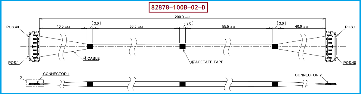
The official documentation for I-PEX 82878-100B-02-D corresponds to a CABLINE-CX II cable harness with specifications of 40Pin, 46AWG, L=200mm, 1-N, and ZenShield type; the matching cable connector model is 20974-040T-01, featuring a 40PIN and 0.25MM pitch connector. The advantage of this structure is that it achieves high-density signal connections within an extremely limited installation space while utilizing a shielding structure to reduce EMI impact. The I-PEX official page also shows that this series uses mechanical latches, has an EMI shielding cover, and a multi-point grounding design, where the cable end shielding can be connected through a grounding rod, male connector shell, shielding cover shell, finally connecting to the female connector shell and PCB to realize a continuous shielding grounding path. Therefore, if the project requirement is for high-speed data transmission, display signals, camera data, board-to-board high-speed interconnections, and so on, engineers can focus on evaluating this ultra-thin coaxial cable harness; if the project requirement involves continuous high current power supply, then the actual load current and the connector current capacity should be recalculated, and not simply add up all the pins because the cable harness has 40 pins and use them directly as "high power supply capacity".
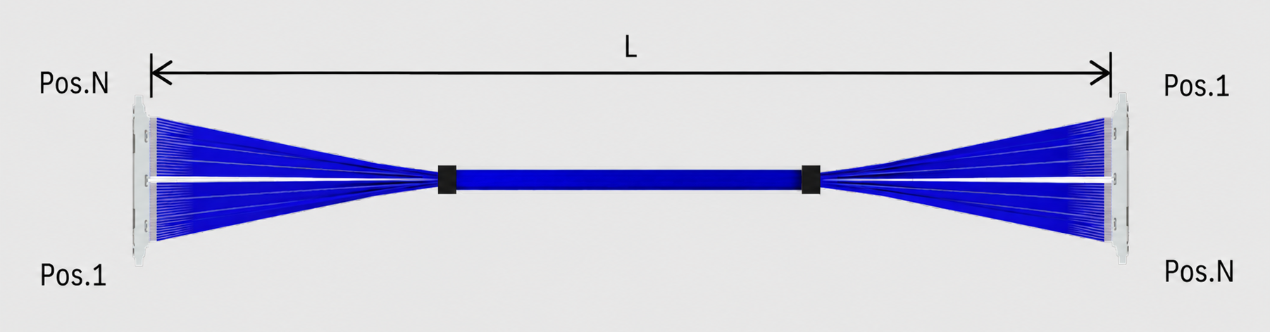
For engineers and procurement personnel who need to achieve domestic substitution, introduce second suppliers, or reduce project costs, I-PEX 82878-100B-02-D can be used as a clear reference model. Key parameters such as connector structure, 40PIN quantity, 0.25MM pitch, 46AWG ultra-thin coaxial wire, 200mm length, wire sequence definition, and shielding grounding structure should be checked item by item. The I-PEX official page lists the CABLINE-CX II With Cover evaluation cables including 82877-100B-02-D, 82439-100B-02-D, as well as 83004-100B-01-D, 83005-100B-01-D, and 83006-100B-01-D with 1-1 wire sequence, which correspond to different lengths and wire sequence configurations. In actual substitution development, it is recommended that procurement personnel clearly provide the original cable part number, connector part number, pin count and pitch, wire specification, finished product length, wire sequence definition, and application current information to the supplier before proceeding with sample sampling and assembly verification, rather than relying solely on appearance for substitution. Our company can provide: I-PEX 82878-100B-02-D compatible alternative cable solution, which can be used for ultra-thin coaxial cable replacement development around the application requirements of 40PIN, 0.25MM pitch, and corresponding wire end connector 20974-040T-01, providing sample verification and alternative selection reference for engineers.
“Without the consent or authorization of this site, no one shall reproduce, reprint, distribute, cite, change, broadcast or publish the content in whole or in part in any form, nor shall there be any other violation of the copyright of this site.