


Categorization:Harness Component
For devices such as high-speed image acquisition, industrial vision, AI vision, and high-resolution display, extremely thin coaxial cables not only undertake the function of signal connection but also directly affect the integrity of high-speed signals. When signals enter the connector from PCB and then enter the extremely thin coaxial cable, if there are obvious impedance discontinuities between different transmission structures, it is easy to produce problems such as signal reflection, increased insertion loss, crosstalk, and waveform distortion. Therefore, engineers should not only focus on the wire diameter, PIN number, and length when choosing extremely thin coaxial cables but also pay close attention to the cable characteristic impedance, connector interface structure, and impedance continuity of the combined area between the connector and the cable. For high-speed links, the so-called "impedance matching" is not simply making two components marked with the same impedance values but as much as possible keeping the entire high-speed signal channel in a continuous and stable transmission environment.
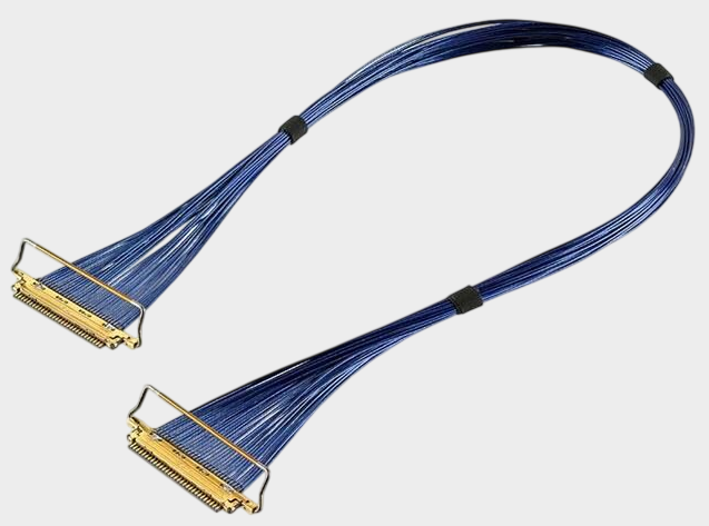
For this product as an example, I-PEX 81422-100B-02-D is a 40PIN extremely thin coaxial cable assembly from the I-PEX CABLINE®-VS series, using AWG#40, 50Ω Micro-Coaxial Cable, with a cable assembly length of 200±5mm, and it belongs to the 1-N structure. The connector model used at the cable end is 20454-240T, employing a 40PIN, 0.5MM Pitch CABLINE®-VS connection structure. It needs to be particularly noted that when I-PEX officially conducted high-speed transmission performance reference tests on the CABLINE®-VS series, they used test conditions with a 40PIN, AWG40 Micro-Coaxial Cable, 45Ω, and 100mm, and obtained a transmission reference result of 32Gbps/Lane NRZ. However, the specific line assembly 81422-100B-02-D is clearly marked as 50Ω. Therefore, in actual projects, engineers cannot simply equate series test data to the ultimate performance of a specific line assembly. Instead, they should conduct a complete SI verification based on the actual cable impedance, length, connector structure, PIN definition, and system PCB design.
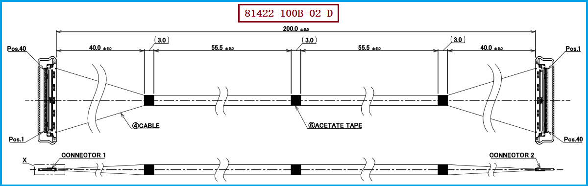
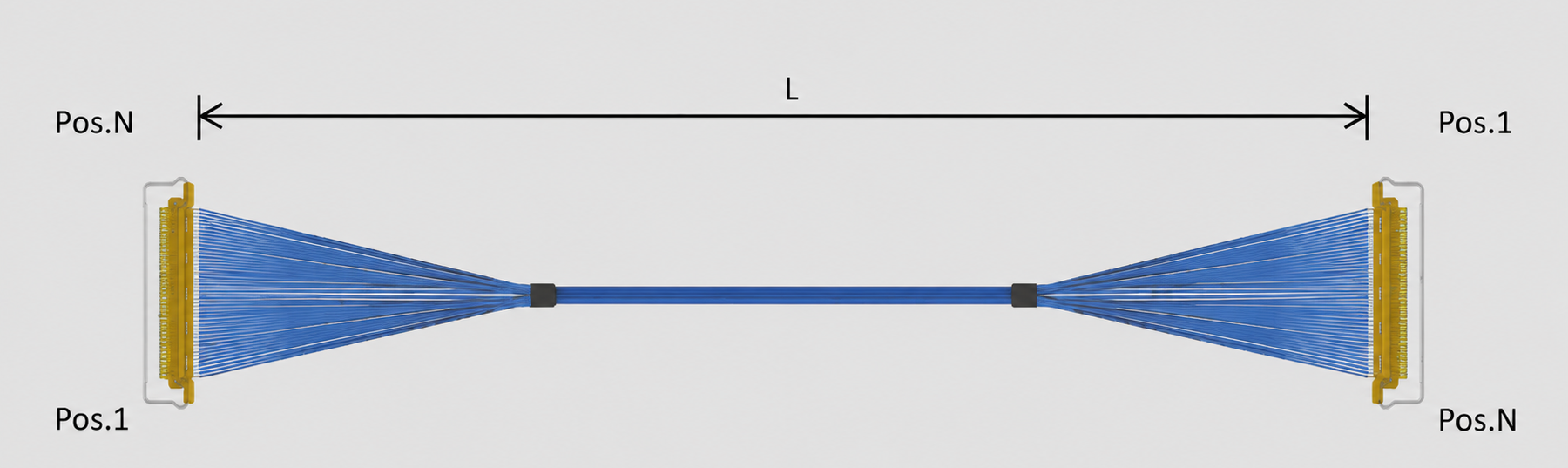
The key to achieving impedance matching usually focuses on the entire signal path of "cable—termination—connector—PCB," rather than just a single component. For high-density connection structures like 20454-240T, 40PIN, and 0.5MM Pitch, it is necessary to maintain a reasonable electrical structure among the terminal arrangement inside the connector, the layout of signal PINs and ground PINs, the extremely thin coaxial shielding structure, the cable termination area, and the PCB pad design. Particularly under the 40PIN high-density layout, changes in the reference ground structure near high-speed signals, or significant geometric size changes in the termination area, may cause local impedance discontinuity. Therefore, for alternative harnesses with structures similar to 81422-100B-02-D, engineers should focus on verifying characteristic impedance, insertion loss, return loss, crosstalk, and TDR impedance curves at different frequencies; they should also pay attention to harness length, wire specifications, PIN assignment, and connector mating relationships to ensure the formation of a continuous transmission path from the cable to the connector and then to the PCB.
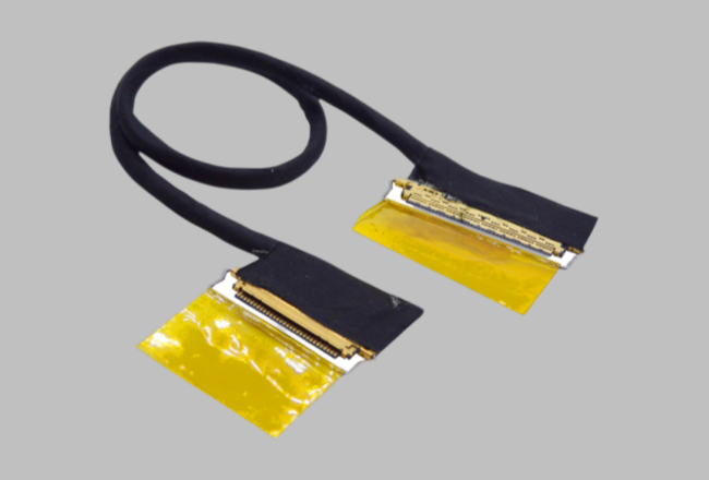
For purchasers, when selecting a compatible alternative cable for I-PEX 81422-100B-02-D, they cannot simply replace it with "40PIN connector + AWG40 wire". Instead, they should check key parameters such as 81422-100B-02-D, 20454-240T, 40PIN, 0.5MM Pitch, AWG40, 50Ω, 200mm, and 1-N wire sequence, and further confirm the connector's appearance size, locking structure, termination process, and PCB mating relationship. For engineers, it is recommended to conduct actual high-speed signal tests at the sample stage, and confirm the impedance continuity and signal integrity of the alternative cable within the target frequency band through TDR, VNA, or system-level SI testing. When purchasing domestic alternatives, it is also recommended to prioritize professional ultra-fine coaxial cable manufacturers that can provide stable wire impedance control, precise termination process, and batch consistency control. Our company can provide: I-PEX 81422-100B-02-D compatible alternative cable solutions, which can be developed for compatibility around the original product's key specifications such as 40PIN, 0.5MM Pitch, AWG40, 50Ω, 200mm, and provide domestic cable selection support for high-speed image acquisition, display, and high-speed data transmission equipment.
“Without the consent or authorization of this site, no one shall reproduce, reprint, distribute, cite, change, broadcast or publish the content in whole or in part in any form, nor shall there be any other violation of the copyright of this site.